- 您现在的位置:买卖IC网 > Sheet目录1013 > XRP6840EVB (Exar Corporation)EVAL BOARD FOR XRP6840
�� �
�
�X� R� P� 6� 8� 4� 0�
�4� .� 3� A� S� u� p� e� r� c� a� p� a� c� i� t� o� r� F� l� a� s� h� L� E� D� D� r� i� v� e� r� w� i� t� h� I� 2� C�
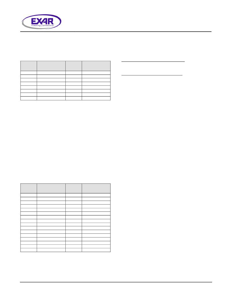
�represent� the� DAC� codes� D2,� D1,� D0.� They� are�
�used� to� set� the� flash� LED� current� levels� in� each�
�channel.� Table� 5� provides� the� DAC� codes� and�
�the� corresponding� nominal� current� levels� for�
�each� channel:�
�Addressing� and� Writing� Data�
�To� write� data� to� the� XRP6840� one� of� the�
�following� two� sequences� is� required:�
�Easy shutdown/startup sequence�
�D2-D0�
�Code�
�XRP6840A�
�I� OUT� /Ch.� (mA)�
�D2-D0�
�Code�
�XRP6840B�
�I� OUT� /Ch.� (mA)�
�[Slave� Address� with� write� bit][Data� for� Status]�
�0�
�0�
�0�
�0�
�1�
�1�
�1�
�0�
�0�
�1�
�1�
�0�
�0�
�1�
�0�
�1�
�0�
�1�
�0�
�1�
�0�
�0�
�400�
�586�
�770�
�948�
�1197�
�1291�
�0�
�0�
�0�
�0�
�1�
�1�
�1�
�0�
�0�
�1�
�1�
�0�
�0�
�1�
�0�
�1�
�0�
�1�
�0�
�1�
�0�
�0�
�597�
�875�
�1127�
�1400�
�1671�
�1910�
�Full shutdown/startup sequence�
�[Slave� Address� with� write� bit][Data� for� Status]�
�[Data� for� LEDFLASH][Data� for� LEDTORCH]�
�Slave� address� is� ‘28’� Hex.�
�1�
�1�
�1� 1445� 1� 1� 1� 2150�
�Table� 5:� Nominal� Flash� Mode� Output� Current�
�Addressing� and� Reading� Data�
�LEDTORCH� Register�
�LEDTORCH� register� bits� B2� to� B7,� also�
�summarized� in� Table� 1;� they� correspond� to�
�LED1,� LED2� and� LED3.� Bits� B4,� B3,� B2,� and�
�B1� represent� the� DAC� codes� D3,� D2,� D1,� D0.�
�They� are� used� to� set� the� torch� LED� current�
�levels� in� each� channel.� Table� 6� provides� the�
�DAC� codes� and� their� corresponding� nominal�
�current� levels� for� each� channel.� Remember�
�that� the� total� current� that� can� be� supported� in�
�torch� mode� is� 600mA� divided� by� the� gain� of�
�the� charge� pump.� If� 2� channels� are� set� to�
�440mA� (a� total� of� 880mA),� even� with� a� gain� of�
�1X,� the� input� current� limit� will� clamp� the� total�
�current� to� approximately� 600mA.�
�To� read� data� from� the� XRP6840� the� following�
�sequence� is� required:�
�[Slave� Address� with� read� bit][Data� for� Status]�
�[Data� for� LEDFLASH][Data� for� LEDTORCH]�
�D3-D0�
�Code�
�XRP6840A�
�I� OUT� /Ch.� (mA)�
�D3-D0�
�Code�
�XRP6840B�
�I� OUT� /Ch.� (mA)�
�0�
�0�
�0�
�0�
�0�
�0�
�0�
�0�
�1�
�1�
�1�
�1�
�1�
�1�
�1�
�1�
�0�
�0�
�0�
�0�
�1�
�1�
�1�
�1�
�0�
�0�
�0�
�0�
�1�
�1�
�1�
�1�
�0�
�0�
�1�
�1�
�0�
�0�
�1�
�1�
�0�
�0�
�1�
�1�
�0�
�0�
�1�
�1�
�0�
�1�
�0�
�1�
�0�
�1�
�0�
�1�
�0�
�1�
�0�
�1�
�0�
�1�
�0�
�1�
�0�
�23�
�46�
�66�
�86�
�105�
�125�
�145�
�165�
�185�
�205�
�225�
�245�
�260�
�280�
�300�
�0�
�0�
�0�
�0�
�0�
�0�
�0�
�0�
�1�
�1�
�1�
�1�
�1�
�1�
�1�
�1�
�0�
�0�
�0�
�0�
�1�
�1�
�1�
�1�
�0�
�0�
�0�
�0�
�1�
�1�
�1�
�1�
�0�
�0�
�1�
�1�
�0�
�0�
�1�
�1�
�0�
�0�
�1�
�1�
�0�
�0�
�1�
�1�
�0�
�1�
�0�
�1�
�0�
�1�
�0�
�1�
�0�
�1�
�0�
�1�
�0�
�1�
�0�
�1�
�0�
�34�
�66�
�97�
�127�
�155�
�185�
�215�
�245�
�275�
�305�
�330�
�360�
�385�
�415�
�440�
�Table� 6:� Torch� Mode� Output� Current�
�?� 2009� Exar� Corporation�
�11/17�
�Rev.� 1.0.0�
�发布紧急采购,3分钟左右您将得到回复。
相关PDF资料
XRP7603EVB
EVAL BOARD FOR XRP7603
XRP7604EVB
EVAL BOARD FOR XRP7604
XRP7620EVB
EVAL BOARD FOR XRP7620
XT374S15
RELAY GEN PURPOSE SPDT 16A 115V
Y0054140K253T29L
RES 140.253K OHM .5W .01% AXIAL
REC5-0505SRW/H2/A/M/SMD
DC/DC转换器 5W DC/DC 2kV REG 2:1 4.5-9Vin 5Vout
Y0065321R00T0L
RES 321 OHM 3W .01% FOIL RAD
Y07061K00000T9L
RES 1.0K OHM .4W .01% FOIL RAD
相关代理商/技术参数
XRP7410EH-F
功能描述:开关变换器、稳压器与控制器 Controller
RoHS:否 制造商:Texas Instruments 输出电压:1.2 V to 10 V 输出电流:300 mA 输出功率: 输入电压:3 V to 17 V 开关频率:1 MHz 工作温度范围: 安装风格:SMD/SMT 封装 / 箱体:WSON-8 封装:Reel
XRP7410EHTR-F
功能描述:开关变换器、稳压器与控制器 Controller
RoHS:否 制造商:Texas Instruments 输出电压:1.2 V to 10 V 输出电流:300 mA 输出功率: 输入电压:3 V to 17 V 开关频率:1 MHz 工作温度范围: 安装风格:SMD/SMT 封装 / 箱体:WSON-8 封装:Reel
XRP7410ERB-F
功能描述:开关变换器、稳压器与控制器 Controller
RoHS:否 制造商:Texas Instruments 输出电压:1.2 V to 10 V 输出电流:300 mA 输出功率: 输入电压:3 V to 17 V 开关频率:1 MHz 工作温度范围: 安装风格:SMD/SMT 封装 / 箱体:WSON-8 封装:Reel
XRP7410ERBTR-F
功能描述:开关变换器、稳压器与控制器 Controller
RoHS:否 制造商:Texas Instruments 输出电压:1.2 V to 10 V 输出电流:300 mA 输出功率: 输入电压:3 V to 17 V 开关频率:1 MHz 工作温度范围: 安装风格:SMD/SMT 封装 / 箱体:WSON-8 封装:Reel
XRP7410EVB
功能描述:电源管理IC开发工具 Eval Board for XRP7410 Series
RoHS:否 制造商:Maxim Integrated 产品:Evaluation Kits 类型:Battery Management 工具用于评估:MAX17710GB 输入电压: 输出电压:1.8 V
XRP7602ERB-F
功能描述:LED照明驱动器 1.2MHz White LED Boost Controller
RoHS:否 制造商:STMicroelectronics 输入电压:11.5 V to 23 V 工作频率: 最大电源电流:1.7 mA 输出电流: 最大工作温度: 安装风格:SMD/SMT 封装 / 箱体:SO-16N
XRP7602ERBTR-F
功能描述:LED照明驱动器 1.2MHz White LED Boost Controller
RoHS:否 制造商:STMicroelectronics 输入电压:11.5 V to 23 V 工作频率: 最大电源电流:1.7 mA 输出电流: 最大工作温度: 安装风格:SMD/SMT 封装 / 箱体:SO-16N
XRP7602EVB
功能描述:电源管理IC开发工具 Eval Board for XRP7602 Series
RoHS:否 制造商:Maxim Integrated 产品:Evaluation Kits 类型:Battery Management 工具用于评估:MAX17710GB 输入电压: 输出电压:1.8 V